
| 일 | 월 | 화 | 수 | 목 | 금 | 토 |
|---|---|---|---|---|---|---|
| 1 | 2 | 3 | 4 | 5 | 6 | |
| 7 | 8 | 9 | 10 | 11 | 12 | 13 |
| 14 | 15 | 16 | 17 | 18 | 19 | 20 |
| 21 | 22 | 23 | 24 | 25 | 26 | 27 |
| 28 | 29 | 30 |
- Manual Handling
- boat parts explained
- 요트제작
- sailing vocabulary
- compositeboat
- boatbuilding
- yacht design basics
- Developable Surfaces
- boatbuilding terms
- shipwright
- boatbuilder education
- Safe Lifting
- marineindustry
- 안전 들기
- 선박용어
- yachtbuilding
- 목공 기계
- 조선용어
- boat terminology
- Study Q&A
- frp보트
- 보트빌딩
- MEM11011B
- 보트빌딩용어
- Bevels
- TAFE Boatbuilding
- TAFE
- marine engineering
- Woodworking Machines
- 선박용어사전
- Today
- Total
The Yachtwright’s Legacy
Review: MEM09021B 곡선형 3차원 형상의 이해와 제작 본문
MEM09021B Interpret and produce curved 3-dimensional shapes
Interpret and Produce Curved 3-Dimensional Shapes
곡선형 3차원 형상의 이해와 제작
Lofting is the process of drawing the hull full-size on a flat floor so that every frame shape, every bevel, and every plank curve can be extracted with precision. It is one of the oldest skills in naval architecture — and one of the most satisfying when it comes together.
로프팅(Lofting)은 선체를 실제 크기(Full Scale)로 바닥 위에 그리는 작업이다. 이를 통해 각 프레임의 형상, 베벨(Bevel) 각도, 그리고 플랭크(Plank)의 곡선을 정확하게 추출할 수 있다. 로프팅은 조선 설계 분야에서 가장 오래된 기술 중 하나이며, 모든 선이 하나의 완성된 선체 형태로 연결되는 순간 큰 성취감을 주는 작업이기도 하다.
📌 Content note: This unit is predominantly practical — much of the learning happens on a lofting floor, not from a textbook. The content here is drawn from the published unit competency standards and well-established lofting and geometric development practice. Nothing is fabricated. Where your class notes differ, trust your instructor first.
📌 내용 안내: 이 유닛은 주로 실습 위주이다. 여기의 내용은 공식 역량 기술서와 확립된 로프팅·기하학적 전개 실무를 바탕으로 한다.
① What is Lofting? · 로프팅이란?
🇬🇧 The purpose of lofting
Scale drawings cannot be used directly for boatbuilding — small errors in the drawing are magnified when you scale up to the real vessel. Lofting solves this by redrawing the hull lines at full (1:1) scale on a flat floor. From this full-size drawing, every shape can be lifted with a template, and every angle can be measured directly.
🇰🇷 로프팅의 목적
축소 도면을 보트 빌딩에 직접 사용할 수 없다 — 도면의 작은 오차가 실물 크기로 확대되면 커진다. 로프팅은 선체 라인을 바닥 위에 실물(1:1) 크기로 다시 그려 이 문제를 해결한다. 이 실물 크기 도면에서 모든 형태는 템플릿으로, 모든 각도는 직접 측정으로 추출할 수 있다.

② Offsets and Plotting · 옵셋과 점 찍기
🇬🇧 What is an offsets table?
An offsets table is a grid of numbers that gives the exact coordinates for key points on the hull — the height of each waterline and sheer at each station, and the half-breadth (width from centreline) at each waterline. These numbers are plotted at full size on the lofting floor to produce the lines plan.
🇰🇷 옵셋 테이블이란?
옵셋 테이블은 선체의 주요 점들의 정확한 좌표를 제공하는 숫자 표다 — 각 스테이션에서 수선과 시어의 높이, 그리고 각 수선에서의 하프 브레드스(중심선에서의 폭). 이 숫자들이 로프팅 플로어에 실물 크기로 찍혀 선도를 만든다.
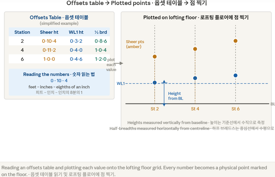
- Chalkline: Snapped onto the floor to create straight reference lines
- Steel square: Sets right angles at each station
- Long straight batten: Checks that straight lines are truly straight
- Small nails/tacks: Driven at each plotted point as physical markers
- Flexible batten: Bent through points to produce fair curves
- 분필선(Chalkline): 바닥에 튕겨 직선 기준선 형성
- 강철 스퀘어: 각 스테이션에서 직각 설정
- 긴 직선 배튼: 직선이 진짜 직선인지 확인
- 작은 못/택: 각 플로팅 점에 물리적 마커로 박힘
- 유연한 배튼: 점들을 통해 구부려 공정한 곡선 생성
③ Fairing Curves · 곡선 페어링
🇬🇧 What is fairing?
After plotting all the points from the offsets table, a long flexible batten is bent through them to produce a smooth, continuous curve. "Fairing" means adjusting the curve until it flows sweetly — no sudden changes of curvature, no flat spots, no "hard spots." If a point forces a kink in the batten, it may need to be slightly moved. This is normal — the offsets table is a starting point, not an absolute.
🇰🇷 페어링이란?
옵셋 테이블의 모든 점을 찍은 후, 긴 유연한 배튼을 구부려 매끄럽고 연속적인 곡선을 만든다. "페어링"이란 곡선이 부드럽게 흐를 때까지 조정하는 것 — 갑작스러운 곡률 변화, 평평한 지점, "딱딱한 지점"이 없어야 한다. 한 점이 배튼에 꺾임을 강제한다면 약간 조정할 수 있다. 이는 정상이다 — 옵셋 테이블은 시작점이지 절대값이 아니다.

④ Developable vs Non-Developable Surfaces · 전개 가능 vs 불가능한 면
🇬🇧 The key concept
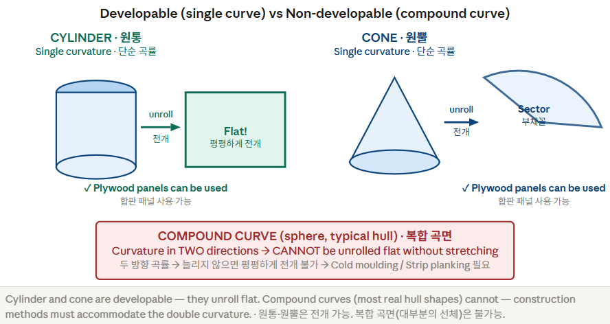
A developable surface is one that can be unrolled flat without stretching or tearing. A cylinder or cone can be unrolled. A sphere cannot — it has curvature in two directions at once (compound curvature). This distinction determines what construction methods are possible: plywood panels work on single-curvature surfaces; cold moulding or strip planking is needed for compound curvature.
🇰🇷 핵심 개념
전개 가능한 면은 늘리거나 찢지 않고 평평하게 펼칠 수 있는 면이다. 원통과 원뿔은 펼칠 수 있다. 구(球)는 불가능 — 두 방향에서 동시에 곡률을 가진다(복합 곡률). 이 구분이 가능한 건조 방법을 결정한다: 합판은 단순 곡률 면에서 작동하고, 복합 곡률에는 콜드 몰딩 또는 스트립 플랭킹이 필요하다.
Identifying curvature type on a hull · 선체에서 곡률 유형 식별
- The hull bends in one direction only at any given point
- A straight batten can be laid flat against the surface in at least one direction
- Typical in hard-chine and multi-chine designs
- Plywood sheet panels fit without forced bending
- 어떤 지점에서도 선체가 한 방향으로만 구부러짐
- 직선 배튼을 최소 한 방향에서 면에 평평하게 댈 수 있음
- 하드 카인, 멀티 카인 설계에서 일반적
- 합판 패널이 강제 구부림 없이 맞음
- The hull curves in two directions simultaneously
- A straight batten cannot lie flat — it always lifts off the surface
- Typical of round-bilge sailing yachts and traditional hull forms
- Requires cold moulding, strip planking, or fibreglass lamination
- 선체가 두 방향으로 동시에 구부러짐
- 직선 배튼이 면에 평평하게 놓이지 않음
- 라운드 빌지 항해 요트, 전통 선체 형태에 전형적
- 콜드 몰딩, 스트립 플랭킹, 유리섬유 적층 필요
⑤ Templates and Bevels · 템플릿과 베벨
🇬🇧 The practical output of lofting
Once the hull lines are faired on the lofting floor, the real work begins: extracting the information needed to cut the actual boat. Templates are physical patterns lifted directly from the lofted drawing. Bevels are the angles at which frame edges must be cut so that the planking beds flat against them. Both are lifted directly from the lofting floor — nothing is re-measured or re-calculated.
🇰🇷 로프팅의 실용적 산출물
선체 라인이 로프팅 플로어에서 페어링되면 실제 작업이 시작된다: 실제 선박을 재단하는 데 필요한 정보 추출. 템플릿은 로프팅 도면에서 직접 들어올린 물리적 패턴이다. 베벨은 프레임 모서리가 플랭킹이 평평하게 안착되도록 잘려야 하는 각도다.
Making a Frame Template · 프레임 템플릿 만들기

Reading a Bevel from the Loft · 로프팅 도면에서 베벨 읽기

⑥ Geometric Development · 기하학적 전개
🇬🇧 What is geometric development?
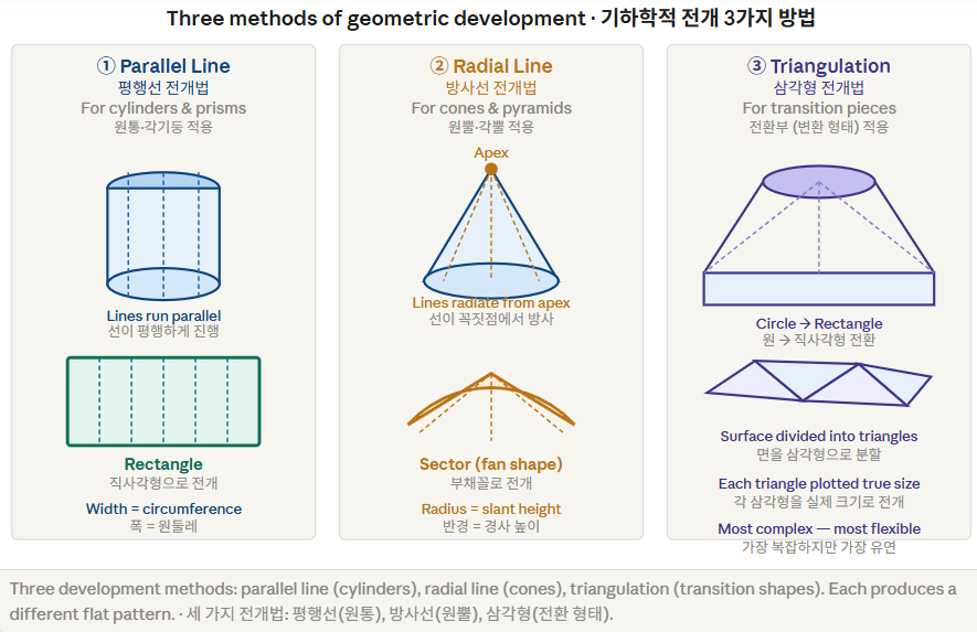
Geometric development is the method of constructing the flat "unrolled" shape of a 3D surface — called the developed surface or development. There are three main methods, each suited to a different type of surface. Understanding which method to use is as important as knowing how to apply it.
🇰🇷 기하학적 전개란?
기하학적 전개는 3D 면의 평평한 "펼친" 형태 — 전개면(development) — 를 구성하는 방법이다. 세 가지 주요 방법이 있으며, 각각 다른 유형의 면에 적합하다. 어떤 방법을 사용할지 아는 것이 적용 방법을 아는 것만큼 중요하다.
Which method to use · 어떤 방법을 사용할 것인가
- Parallel line: The surface has parallel edges (lines of the surface are all parallel). Cylinders, prisms, any shape that extrudes uniformly.
- Radial line: The surface tapers to a point (or can be extended to a point). Cones, pyramids, transitions that taper evenly.
- Triangulation: The surface has no parallel lines and does not taper to a single point. Transitions from one shape to a different shape. More laborious but works on any surface.
- 평행선법: 면의 모서리가 평행한 경우. 원통, 각기둥, 균일하게 돌출되는 형태.
- 방사선법: 면이 한 점으로 수렴하거나 연장하면 수렴하는 경우. 원뿔, 각뿔, 균일하게 가늘어지는 전환부.
- 삼각형법: 평행선도 없고 단일 점으로 수렴하지도 않는 경우. 한 형태에서 다른 형태로의 전환. 더 번거롭지만 모든 면에서 작동한다.
'Marine Composites' 카테고리의 다른 글
| Review: MEM11011B 인력 부하 작업시 유의 사항 (1) | 2026.06.04 |
|---|---|
| Review: MEM09002B 설계도 해석 (1) | 2026.06.02 |
| Review: MEM08011B 용제 및 기계적 방법을 이용한 표면 처리 (1) | 2026.06.01 |
| Review: MEM07001B 기계 및 장비 기본 유지관리 (0) | 2026.05.29 |
| Review: MEM04018B 목공 기계 운용 기초 (0) | 2026.05.26 |


